power flame burner wiring diagram
The fuel oil pump is remote on all. X4 X4M Installation and Operation Manual - POWER FLAME INCORPORATED 1 1.
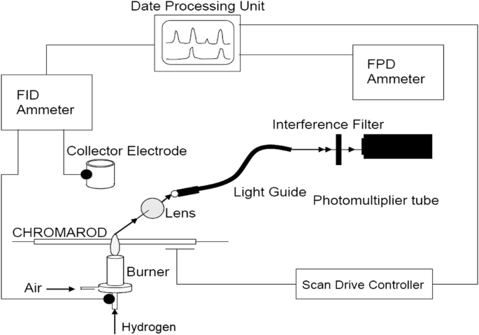
Thin Layer Chromatography Flame Ionization Detection Springerlink
We manufacture a wide range of commercial burners industrial burners boiler burners.

. Loose connections or faulty wiring. Atwood Furnace Wiring Diagram. 62Electrical installation must be made in accordance with the NEC NFPA 70 or Canadian Electrical Code Part 1 and applicable.
Power flame wiring diagram Diagram together with GM HEI Ignition Module Wiring Diagram. General 211 Before beginning installation carefully study these instructions and all charts drawings and diagrams shipped with the burner. Burner Director Management Boiler Burners Power Flame.
Figure 4 C Lr Internal Wiring Diagram End Vent Burner Manualzz. Each Power Flame VECTOR burner is factory test fired to ensure that components and systems are functional. Extinguish any open flame.
Because each field application is unique the final burner set-up. 14 Pics about Diagram together with GM HEI Ignition Module Wiring Diagram. Figure 1 Burner Component Identification Typical for Model CR-GO with On-Off FuelAir Control Modes of Operation The components and arrangements shown are typical for a Model CR.
Click here for the Power Flame library. POWER FLAME INCORPORATED If you smell gas. Reset and determine cause for apparent flame failure.
Comprehensive wiring diagrams are furnished with each burner. The Power Flame Model CGO dual fuel burner presents an optimum state-of-the-art design for maximum combustion efficiency and operating dependability These packaged combustion. WIRING 61 Refer to wiring diagram shipped with burner.
61 Refer to wiring diagram shipped with burner and typical wiring diagrams Figures 5 and 5A. 6 WIRING 61 Refer to wiring diagram shipped with burner. Charger hp diagram hstnn ca15 circuit.
GENERAL INFORMATION 11 The X4 burner is a new generation of gas power burners designed to fire. Special panels for wall mounting or free standing applications are available at extra cost. Do not touch electrical switches.
Tighten all terminal screws and consult. If supplied 62 Electrical installation must be made in accordance with National Electrical Code and applicable local codes. Cmax Manual Rev 0217 A.
Call your gas supplier immediately. The two power leads black and white are located inside the burner panel. Flame safeguard control safety switch tripped out.
61 Refer to wiring diagram shipped with burner and typical wiring diagrams Figures 5 and 5A. The two power leads black and white are located inside the burner panel.
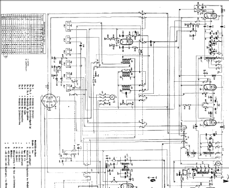
15 Watt Sender Empfanger 15 24b 124 Mil Trx Militar Verschiedene
Gas Burner Primary Control Heater Service Troubleshooting

Bell Sound 2154a Power Amplifier Schematic Electronic Service Manuals

Furnace Power Flame Incorporated Oil Burner Gas Burner Circuit Board Graphics Schematic Combustion Png Pngegg
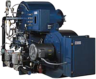
Powerflame Boilerdata Com

West Auctions Auction Online Tenant Abandonment Auction In San Pablo Ca Item Power Flame Burner Model J30a 10 And Zhongda No 99071503
M8079 Gif
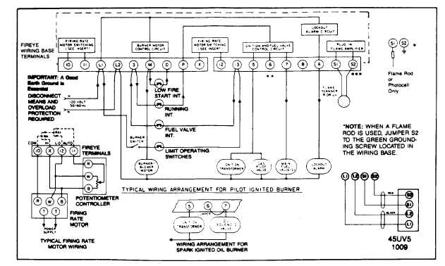
Suggested Wiring Diagram For Fireye Ep260 Ep261 Ep270 Programmer Logic
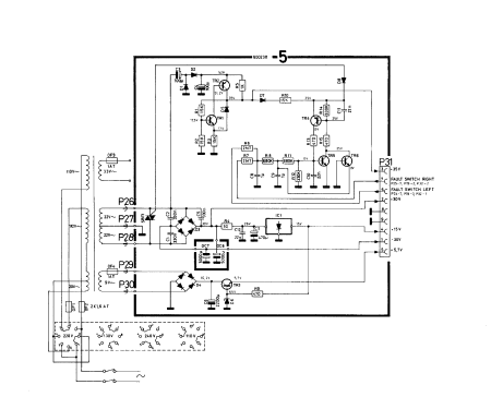
Beomaster 2200 1601 Radio Bang Olufsen B O Struer Build

Burners Preferred Utilities Mfg

Bunton Bobcat Ryan 930000 Power Unit 14 Hp Kohler Gear Drive Parts Diagram For Kohler Wire Harness

Gas And Temperature Control For Dummies Home Brew Forums Circuit Diagram Control Diagram
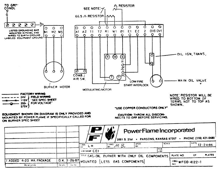
Gas Oil Burner With Only Oil Components Mounted Less Gas Components

Experimental Set Up For Measurement Of Breakdown Electric Field Download High Resolution Scientific Diagram
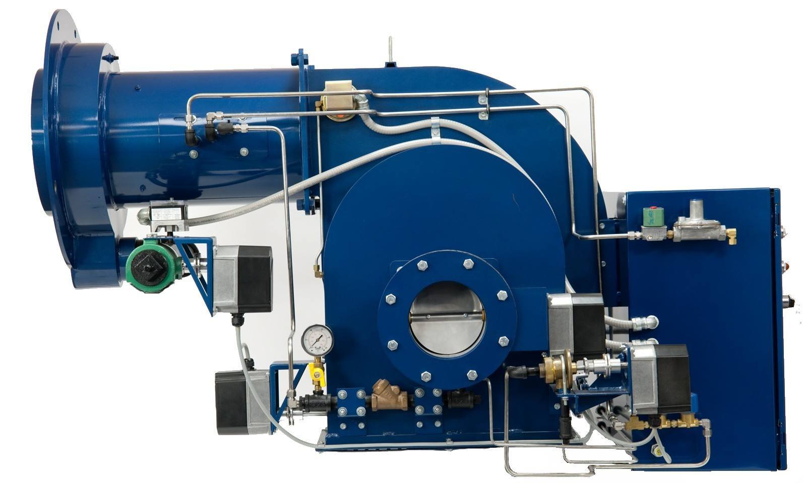
Power Flame Commercial Industrial Burners Ati Of Ny

How To Read Furnace Wiring Diagram Youtube
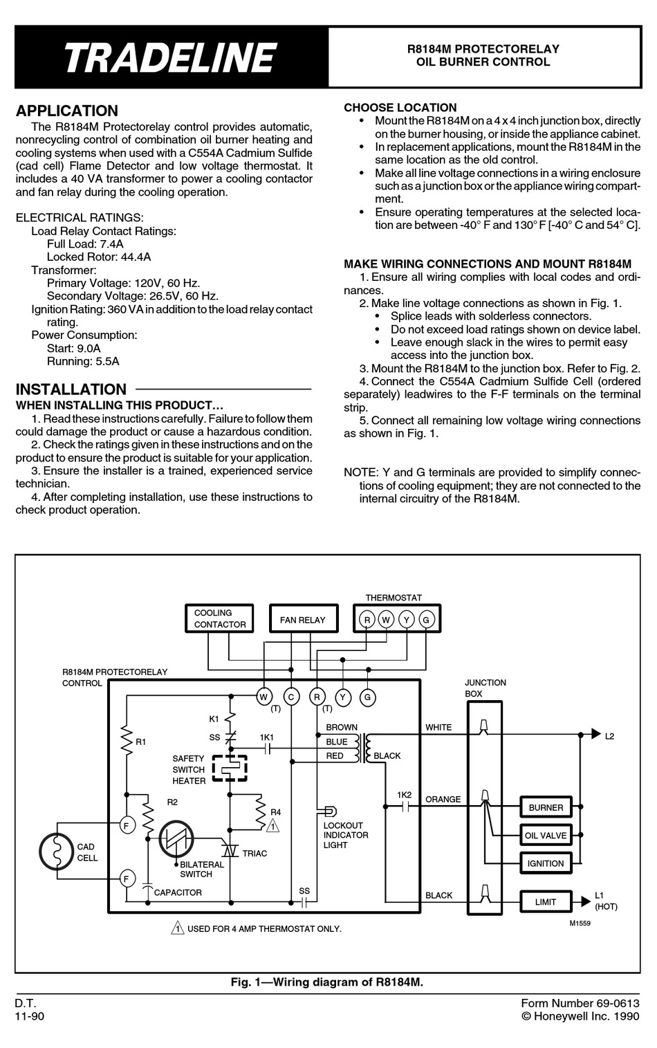
Honeywell R8184m Manual Pdf Download Manualslib